wtorek, 4 kwietnia 2017

Digitally controlled power supply [9001]

Finally I've made something, that is worth presenting. But first, let's start with quick introduction.
The power supply which I was building almost for a two years is finally at end stage of development.

Current stage of events

 That's the 3rd iteration of PCB for this project.

I divided this PCB onto4 separate blocks:
1) The switch mode pre-regulator,

2) Linear post-regulator,
3)  uC with peripherals,
4)  Power conditioning for uC and Op-amps.

colors: yellow - buck regulator, orange - linear regulator, black - uC, violet - power conditioning

The main idea is to create for linear regulator around 1.5V headroom for proper operation. It is made by double diode drop which then regulates buck converter.

Tracking by means of simple transistor


Coarse voltage is then feed to pass MOSFET which stabilize output voltage.


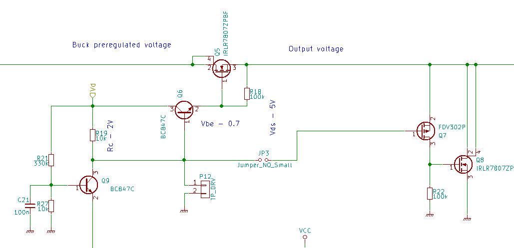
Shunt regulator is on the right.

In addition to series regulation I provided means for shunt stabilization - in case someone puts charged capacitor.

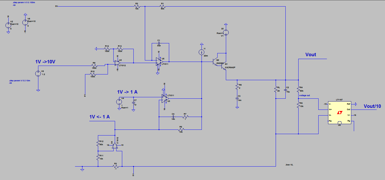
For feedback loop I've  used two quad op-amps. One of them is responsible for voltage stabilization, while the second is responsible for current limitation.

Set values are given by ATXmega's DAC which handles also readout of current values as well as communication with PC. The next step will be creation of LCD front panels with knobs and rotary encoder to ease relations with PSU.

Here is entire schematic. My goal is to refine it as well as layout and then publish next version.
Someday...
https://www.dropbox.com/s/d2y9hc7o3az79o0/schematicBlog.pdf?dl=0

Thanks for reading, I really appreciate it! All comments regarding electronics and grammar are mostly welcome! :)

środa, 30 marca 2016

Digitally controlled power supply [2] - one does not simply make PSU

           I am ([Update 01-05-2016] rejuvenated and eager to find new opportunities! :) Finally The pcb arrived.) tried of chasing my desire to create the best, the cheapest, the smallest (and so one) power supply. Right now it's about 9 months since I've started thinking about it. There is no physical outcome for that work (except for valuable knowledge, of course). I have spent dozens of hours in LTspice, Kicad and Supplier's Website to have all worked out...

           I am not writing this, because I like to lament to others; rather I want that this entry will enforced me to make some progress.

I will update this every time I'll make something:

  • [30-03-2016] I'll create psu based on LB-28 ( http://www.ti.com/lit/an/snoa692/snoa692.pdf ) Some parts are obsolete, but I've found pin-to-pin replacements. Nevertheless I am little worried about compensation network...
  • [01-05-2016] PCB arrived. Waiting for components.


środa, 20 stycznia 2016

Digitally controlled power supply [1] - analog board

I've spent a huge amount of time making a PSU which satisfies my requirements:
  • voltage set and read resolution: ~1mV
  • current set and read resolution: ~1mA
  • set parameters controlled with ease by DAC.
  • easy readout by ADC
  • max current: ~ 2-3A 
  • max voltage: ~ 20-24V
  • possible to track outputs.
  • relatively cheap solution. (Linear Technology has an uber-sample program which allows you to send samples even if you have a commercial e-mail. (I've received samples while using Gmail).
I've focused the most onabsolute accuracy; other requirements were less important.

After gazillion of hours spending in LTspice I've managed to bring this monster alive:


The thing that drived me nuts the most was stabilizing feedback network. I don't know if it is property of high-side current measuring using LTspices macro-model, but every solution which utilized it, falls. So I've tried with low-side current sense. After some tweaking I released that this path doesn't make thing hairier - no addition OP amp I've used.

Program says about 0.2mV accuracy which is fairly optimistic prediction. I haven't done prototype already, but with my poor PCB routing skills; susceptibility to ground loops I don't except accuracy higher than 10mV.

There is link to file. If you wanna changed it or whatever, you are free to go:
my dropbox

poniedziałek, 21 września 2015

[EN] Xmega - Development board


Hello.

I've just finished build my Xmega128a3u Dev board.
It offers:

  • USART 
  • USB
  • TWI, aka I2C
  • Atmel DataFlash
  • 4x pushbuttons
  • 4x LED
  • SD card slot
  • 2 analog ports with exteral clamping diodes (PORTA & PORTB)
  • 1 digital port with current limiting resistor (PORTF)
  • External voltage reference

It can be programmed via PDI, or USB (using bootloader). Also it have two sources of power:
  1. From DC adapter - up to 12V
  2. From USB - with circuit which prevents overshoot

Ovierview of board:

TOP:


BOTTOM:


There are some unpopulated pads - it's because I have ordered wrong size of resistor ladder, but it isn't so crucial - just for digital IO.
Surely they will fit. :)

...and bodge wires. First is well visible:


Second one caused USART to stop working. I've forgotten add trace to Vcc from nearby via (pin 9):


Overview with grouped parts and its purpose: