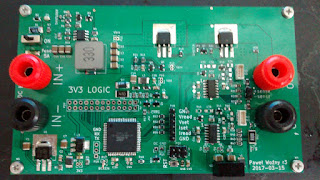
The power supply which I was building almost for a two years is finally at end stage of development.
 |
| Current stage of events |
That's the 3rd iteration of PCB for this project.
I divided this PCB onto4 separate blocks:
1) The switch mode pre-regulator,
2) Linear post-regulator,
3) uC with peripherals,
4) Power conditioning for uC and Op-amps.
 |
| colors: yellow - buck regulator, orange - linear regulator, black - uC, violet - power conditioning |
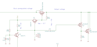
The main idea is to create for linear regulator around 1.5V headroom for proper operation. It is made by double diode drop which then regulates buck converter.
| Tracking by means of simple transistor |
Coarse voltage is then feed to pass MOSFET which stabilize output voltage.
 |
| Shunt regulator is on the right. |
In addition to series regulation I provided means for shunt stabilization - in case someone puts charged capacitor.
For feedback loop I've used two quad op-amps. One of them is responsible for voltage stabilization, while the second is responsible for current limitation.
Set values are given by ATXmega's DAC which handles also readout of current values as well as communication with PC. The next step will be creation of LCD front panels with knobs and rotary encoder to ease relations with PSU.
Here is entire schematic. My goal is to refine it as well as layout and then publish next version.
Someday...
https://www.dropbox.com/s/d2y9hc7o3az79o0/schematicBlog.pdf?dl=0
Thanks for reading, I really appreciate it! All comments regarding electronics and grammar are mostly welcome! :)